
Machinery Corner Jacking:
Which Other Corner Gets Heavier?
Home » Technical Library » Load Distribution & Final Positioning » Jacking One Corner? Here’s Which Other Corner Gets Heavier
By Machinery Sliders™ Technical Team|Drawing on industry background in machinery rigging and moving equipment|Last Updated: November 8, 2026
Direct Answer: You Lifted One Corner. Which Other Corner Got Heavier?
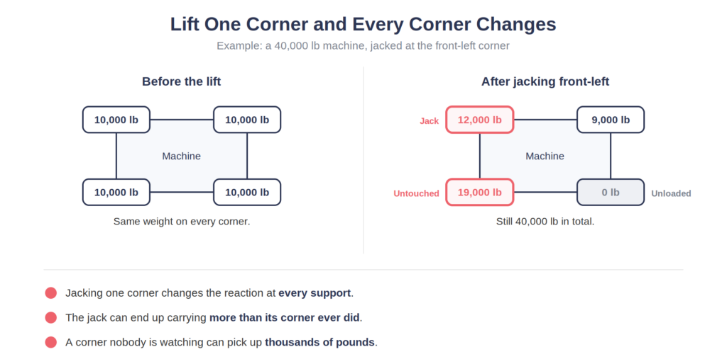
Corner jacking changes the reactions at every other support, not just the one you’re lifting. The machine’s total weight never changes, but where that weight goes absolutely does — a jack can end up carrying more than its corner’s original share, an adjacent support can unload almost completely, and a support you never touched can pick up thousands of pounds you weren’t watching. “We’re only lifting this corner” is almost never actually true.
Forget "Weight Divided by Four"
A 40,000 lb machine on four supports doesn’t automatically put 10,000 lbs on each one — that answer only holds under a perfectly idealized setup: centered center of gravity, matched support elevations, and reactions that happen to distribute equally. In the field, those conditions rarely all hold at once. The math has to satisfy two things at once: all the upward reactions have to add up to the machine’s total weight, and those same reactions have to balance the machine’s tendency to tip around its center of gravity. There are infinitely many combinations of four numbers that add up to 40,000 — the real distribution depends on where the weight actually sits, not on how many supports there are.
A simple two-support example: a 40,000 lb machine spans 10 feet between a left and right support. If the center of gravity sits 4 feet from the left support, the right support carries 40,000 × 4 ÷ 10 = 16,000 lbs, and the left carries the remaining 24,000 lbs. The machine can be perfectly level while one support carries 50% more than the other. Shift the center of gravity to just 2 feet from the left support, and the split becomes 32,000 / 8,000 — one side now carries four times the other.
When Corner Jacking Starts, the Load Has to Go Somewhere.
As a corner lifts clear, the machine can temporarily behave like it’s resting on three points instead of four — the jack, and two of the remaining original supports — while the fourth original support unloads. Which three points end up carrying the load depends on the machine’s stiffness and the jacking sequence, and the corner diagonally opposite the jack is mechanically involved even though nobody touched it, the same way pushing up one leg of a four-legged table changes the load relationship at the other legs.
Worked example: starting reactions are 10,000 lbs on each of four corners (40,000 lb total). You jack front-left. Once it’s fully lifted, suppose the jack carries 12,000 lbs and front-right carries 9,000 lbs. Since all reactions must still add to 40,000, rear-left must be carrying 19,000 lbs — nearly double its starting load. Nobody touched rear-left. Nobody may even be watching it. But 9,000 lbs migrated there.
This is why “the other three should just share the unloaded weight evenly” is often wrong — actual redistribution depends on moment balance and distance from the pivot, not a simple three-way split. See our page on how a level machine can still have unequal loads for the same underlying principle applied to travel instead of jacking.
The Jack Can End Up Carrying More Than the Original Corner Ever Did
A corner that started at 8,000 lbs doesn’t cap the jack at 8,000 lbs — as the machine rises, support geometry changes, and the jack can end up taking 10,000, 12,000, or more depending on the machine. Jack capacity needs to be based on the maximum reaction the jack could realistically see during the whole lift, not the estimated original foot load — if your calculation says the jack might see 9.8 tons, a 10-ton jack leaves almost no margin for center-of-gravity uncertainty, friction, or the load migration this whole guide is about.
Jack Position Matters as Much as Jack Capacity
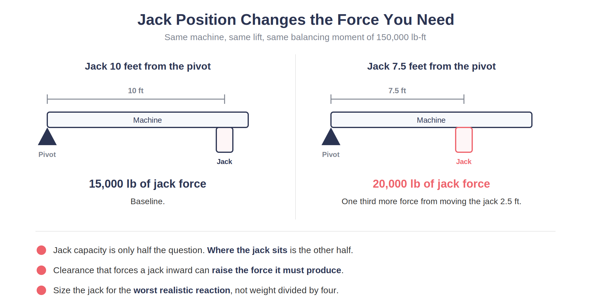
Worked example: a required balancing moment of 150,000 lb-ft, resisted by a jack 10 feet from the pivot, needs 150,000 ÷ 10 = 15,000 lbs of jack force. If clearance forces the jack 2.5 feet closer in (a 7.5-foot lever arm instead), the same moment now needs 150,000 ÷ 7.5 = 20,000 lbs — one-third more force, from moving the jack 2.5 feet. Same machine, same weight, same lift — a different jack location changed the required force by 33%.
Tiny Movement Can Mean Enormous Force Change
In a genuinely stiff support system, force and deflection are related roughly as force = stiffness × movement — meaning in a very rigid structural path, a relative movement of just a few hundredths of an inch can correspond to a change of thousands of pounds of reaction. That’s why a jack can pump easily for a while and then suddenly get hard: the machine’s actual support geometry just reorganized, even though the visible lift barely changed. See our page on why a jack can walk or tilt while the machine looks still for the companion lesson — watching the jack itself, not just the machine, for signs something’s changing.
Hydraulic Pressure Is Useful — With the Right Context
Force from a hydraulic cylinder is roughly pressure times the cylinder’s effective piston area, so a pressure rise from 2,000 to 3,000 psi on the same cylinder represents roughly a 50% increase in jack force — real, useful information, especially if the machine barely appears to have risen. But equal pressure across multiple jacks doesn’t mean equal force unless the cylinders have the same effective area — know your equipment before comparing gauge readings across jacks. This is exactly why hydraulic lifting equipment manufacturers commonly recommend individual gauges at each lift point in a multi-point system: it’s the only way to actually see how load is distributing, rather than assuming it.
The Overloaded Component Is Often Not the Jack
Worked example: a 30,000 lb machine is being corner-jacked. Measurements show one remaining support at 2,000 lbs, another at 7,000 lbs, and the jack itself reading 9,000 lbs. Since everything must add to 30,000, the final remaining support must be carrying 30,000 − 9,000 − 2,000 − 7,000 = 12,000 lbs. If that support is rated for only 10,000 lbs, it’s overloaded by 20% — and it’s not the jack, and probably not the support everyone was watching.
Machinery Sliders Reduce Lift Height, Not the Underlying Physics
A single-direction Machinery Slider often needs only about 3/8″ of installation clearance, and that low profile is a genuine advantage — less required lift generally means less geometric change, less machine rotation, and shorter exposure to the whole redistribution process described here. But the machine still weighs exactly what it weighed before, and even a 3/8″ lift is enough to unload a support, shift a jack’s effective contact point, or move the center of gravity relative to the support plane. Low lift height reduces exposure to this problem — it doesn’t exempt you from planning for it, and jacking higher than the moving system actually requires only increases the exposure unnecessarily.
Watch the Whole Machine, Not Just the Jack
The diagonal corner, the adjacent supports, the frame, and the floor beneath every support all deserve attention during a lift — not just the jack’s gauge. A camera on the far corner while the jack operator watches pressure is a genuinely good use of remote observation here, and one person should have overall authority over the lift rather than several people independently deciding to “give it another pump.” Lift in small planned increments, stop, observe, and only then continue.
Before Corner Jacking: A Checklist
- What is the machine’s total weight and approximate center of gravity?
- What is the maximum reaction the jack could realistically see — not just weight divided by four?
- Is the jack positioned at the original support point, or has clearance forced it inward, changing the lever arm?
- Which other support is most likely to unload, and which is most likely to pick up that load?
- Are all remaining supports individually rated for their possible peak reaction, not just their assumed starting load?
- Is cribbing ready before the lift, and will the load be secured promptly once raised?
Stop and reassess if: jack force exceeds your prediction, hydraulic pressure rises sharply without expected movement, another support unloads or overloads unexpectedly, the machine begins rocking on a diagonal, or the load distribution no longer matches the plan. Don’t answer an unexpected reaction with a bigger jack until you understand why the original estimate was wrong.
Learn More: Frequently Asked Questions
Not necessarily. The actual reaction depends on center of gravity, support geometry, stiffness, and jack location.
Yes. As support geometry changes during the lift, the jack’s share can increase beyond the original static reaction.
Yes. Load redistribution during jacking isn’t limited to adjacent supports — the diagonal corner is often the one that changes most.
Because required force depends on force times distance from the pivot — moving the jack closer to the pivot increases the force needed for the same balancing moment.
Only if the cylinders have the same effective piston area — otherwise equal pressure can still mean very different actual forces.
Yes. Even a 3/8″ lift can unload a support or shift the center of gravity relative to the support plane.
No. It can reduce the amount of lift required, which reduces exposure, but correct jack placement, capacity, and load-transfer planning are still necessary.
Final takeaway: you don’t jack only one corner — you change the entire support system. Before pumping the handle, don’t just ask what the jack will carry. Ask the harder question: when this corner comes up, which other corner gets heavier? The most dangerous force in a corner-jacking operation is often not the one you’re watching.