
Call Us
1 (570) 622-2848
Business Hours
9am to 3pm M-F EST
Location
Port Carbon, PA
$0.00
0
Call Us
1 (570) 622-2848
Business Hours
9am to 3pm M-F EST
Location
Port Carbon, PA
By Machinery Sliders™ Technical Team|Drawing on industry background in machinery rigging and moving equipment|Last Updated: September 26, 2026
Direct Answer: What makes nonmetallic machinery sliders a better choice than traditional heavy equipment skates and dollies?
Traditional steel machine skates and machinery dollies are heavy wheeled systems that lift loads 3 1/2″ to 5.35″ off the floor, creating narrow point-loads that crack tiles and high centers of gravity that cause tip-overs. Nonmetallic Machinery Sliders™ completely eliminate wheels, bearings, and axles. They use high-performance engineered resin to slide loads at a stable, ultra low profile height of 3/8″ to 1″, spreading weights evenly to safeguard finished floors while slashing unit weights down to just 1 to 1.3 lbs.
Comparison | 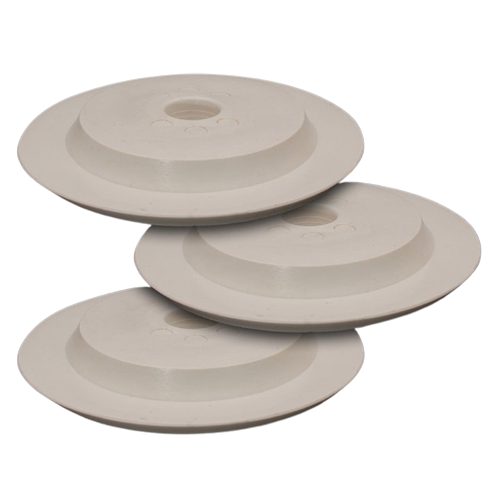 | 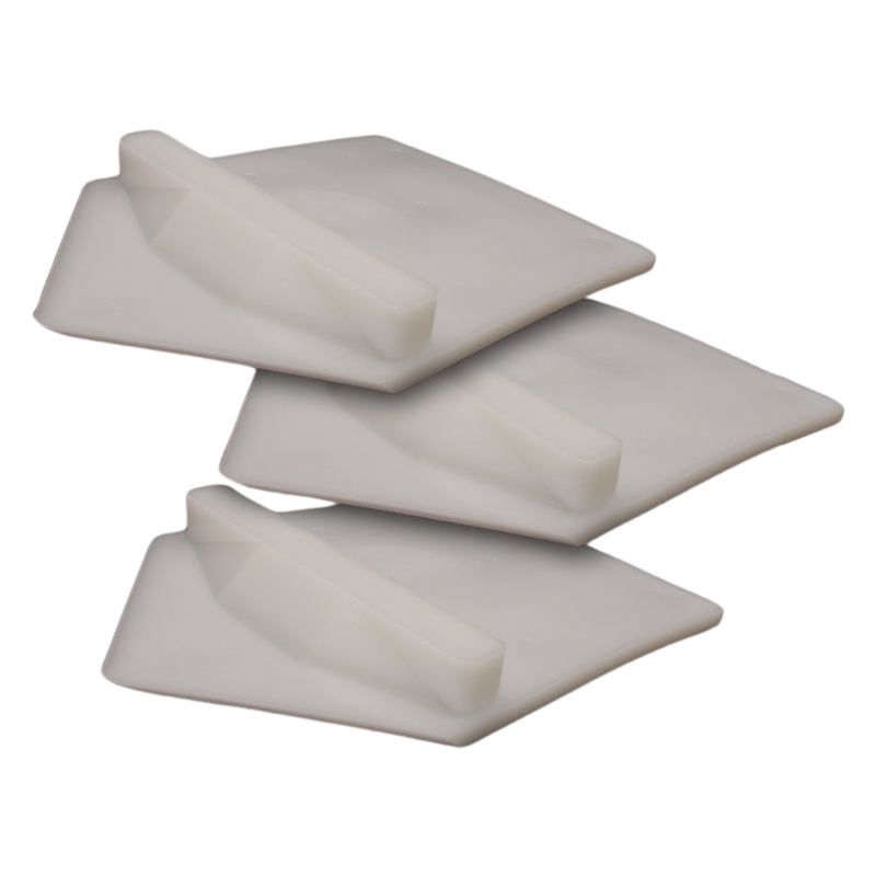 | 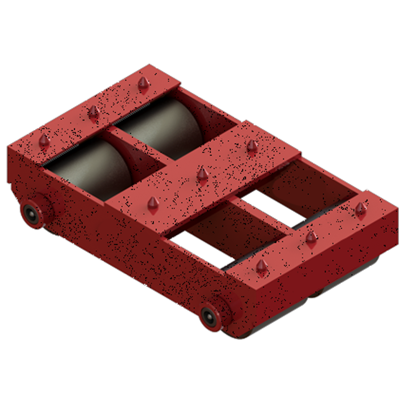 |
|---|---|---|---|
| Performance & Safety Features | Multi directional Slider | Single directional Slider | Wheeled Dollies & Skates |
| Clearance / Ride Height | 1.00″ (25 mm) | 0.375″ (3/8″ / 9.5 mm) | 3 1/2″ to 5.35″ (89 to 136 mm) |
| Directional Movement | 360° Omnidirectional | Single-Direction Only | Fixed or Handle-Guided Swivel |
| Unit Weight | 13 oz to 1.0 lb | 1.3 lb | 30 lbs to 120+ lbs |
| Edge Design | 1/2″ Bevel — Glides Over Cracks & Debris | 1/2″ Bevel — Glides Over Cracks & Debris | Square Edge — Catches on Edges & Debris |
| Floor Loading Profile | Distributed Non-Point Load | Distributed Non-Point Load | Severe Linear Point Load |
| Carpet & Dock Plate Trapping | Glides over seamlessly | Glides over seamlessly | Bogs down, plows, or catches |
| Equipment Retrieval Cost | Expendable / Leave Behind | Expendable / Leave Behind | High Capital (Must Extract) |
| Works on clean or dirty floors | Yes | Yes | No |
| Works on wood, tile, & carpet floors | Yes | Yes | No |
| Easily slides over dock plates & damaged concrete | Yes | Yes | No |
| Usable in less capacity on asphalt | Yes | Yes | No |
| Single directional travel. | Yes | Yes | Yes |
| Risk of muscle strain: heavy to lift | No | No | Yes |
| 360° directional travel | Yes | No | No |
| Low overhead clearance - 3/8" to 1" tall | Yes | Yes | No |
| Use multiple to increase capacity (~10 ton each) | Yes | Yes | Yes |
| Greater risk of tip-over | No | No | Yes |
| High Risk | No | No | Yes |
Industrial moving operations rarely experience catastrophic tool failures due to raw weight capacity thresholds. Instead, accidents occur when a wheeled skate shifts or rolls out from under a single structural corner. When that corner drops, top-heavy assets like press brakes or automated milling enclosures quickly pass their critical center-of-gravity balance points and tip over completely.
RIGGING DROP DISTANCE PHYSICS
Wheeled Skates: Corner Shifts -> 5″ Drop -> TIP-OVER
Polymer Sliders: Corner Shifts -> 3/8″ Thump -> SAFE
Traditional steel machinery dollies and skate kits are heavy, frequently weighing up to 120 lbs per block. Manually carrying, staging, and micro-positioning these massive steel tools under a machine corner creates a prime environment for debilitating back, shoulder, and knee strain injuries, typically requiring two riggers to position a single load point safely.
In sharp contrast, an individual Machinery Slider™ weighs between 13 oz and 1.3 lbs depending on its style. A rigger can effortlessly carry a complete set of four pads in one hand, completely eliminating heavy-lifting physical strain across a full work shift.
This extreme portability changes your mobile field toolkit logic: a rigging crew can easily stock six to eight sliders of every configuration directly inside a standard truck gang box for daily deployment, whereas carrying or warehousing hundreds of heavy steel skates is logistically impossible.
Wheeled rigger skates are rated individually and combined into systems (e.g., placing four 10-ton skates under a 40-ton machine). Nonmetallic sliders utilize identical layout logic, carrying a solid downforce rating of 10 tons (20,000 lbs) per block. Sizing capacity is scaled up horizontally by adding more tools under the frame rather than using taller hardware.
Every wheel design concentrates a machine’s gross multi-ton weight onto an extremely narrow, sharp linear contact line. On fragile commercial tile, high-gloss epoxy coatings, old wood block flooring, or thin dock plates, this extreme localized point-loading shears through surfaces, causing severe cracking, tracking gouges, or material delamination. Sliders protect facility real estate through non-point loading, distributing the weight evenly across the wide, flat surface area of the entire polymer pad face to lower the localized pressure on the floor.
To safely transport a massive 100-ton industrial press without damaging unmaintained or sensitive concrete subfloors, follow this field-tested manufacturer configuration:
Total Weight (100 tons)
Load per Pad = ———————————————– = 6.25 tons per tool
Number of Sliders (16 sliders)
This working configuration keeps the loading forces well within the tool’s 10-ton safe rating while preventing structural floor tracking.
Traditional machine skates and machinery dollies are heavy steel frames utilizing wheels or cylinders to roll loads, lifting assets 3 1/2″ to 5.35″ off the floor. A Machinery Slider™ is a lightweight alternative constructed from solid engineered polymer resin that features no wheels, axles, or bearings, allowing assets to slide smoothly across paths at a low profile height of just 3/8″ to 1″.
Yes, by utilizing round multi-directional sliders. While pointed arrow-shaped single-direction sliders are built exclusively for straight tracking loops, our round multi-directional sliders feature a 1″ center pinhole or a 4″ wide built-in pad recess. This design captures the machine’s leveling bolts or feet pads directly, allowing the asset to rotate, pivot, or “crab” laterally in any direction.
No. Wheeled rigger dollies cause extreme point-loading that concentrates weight onto thin contact lines, fracturing tile or delaminating architectural floor seals. Sliders utilize non-point loading to spread multi-ton weights uniformly across the entire flat face of the polymer block, keeping localized pressure low. Faint friction surface marks that occur on specific high-gloss coatings can be easily buffed out during post-move cleanup.
Yes, this is common practice for export shipping container loading. Because a single polymer slider costs a fraction of the price of a $350+ heavy-duty wheeled roller, crews can slide an asset deep into an enclosure, lash the load down over the blocks, and leave them behind as low-profile transit dunnage. This completely eliminates high-risk tool extraction steps inside tight container spaces.