
Call Us
1 (570) 622-2848
Business Hours
9am to 3pm M-F EST
Location
Port Carbon, PA
$0.00
0
Call Us
1 (570) 622-2848
Business Hours
9am to 3pm M-F EST
Location
Port Carbon, PA
$142.97
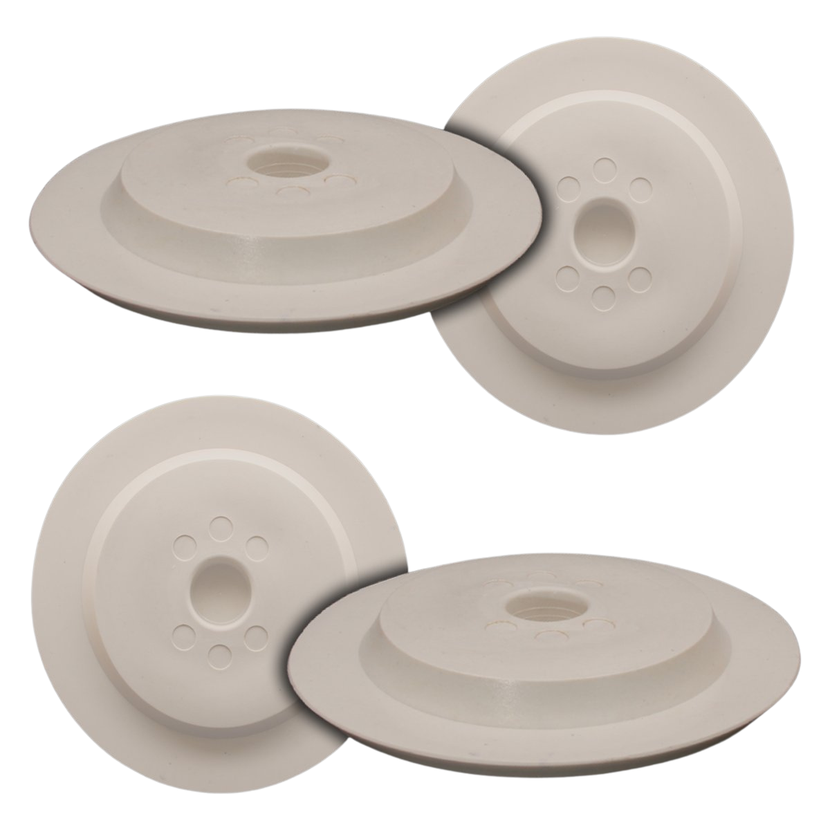
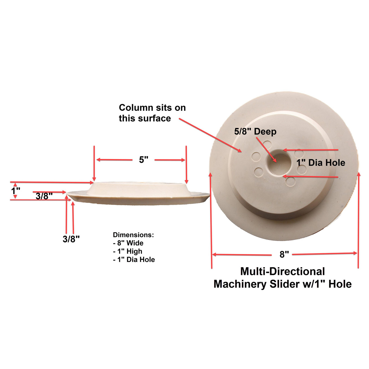
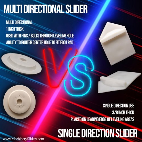
The Multi-Directional Machinery Slider Set includes four 100% non-metallic machinery slider skates designed for moving, turning and positioning heavy machinery in multiple directions. Each slider weighs 1.0 lbs (0.45 kg) and measures 8″ in diameter × 1″ high with a 1″ round center hole designed for an appropriate pin or bolt to positively retain the slider beneath the machine during multidirectional movement. The machine column, leg or support point rests on a 5″-diameter top support surface.
A 1/2″ beveled perimeter helps the slider transition over uneven floors, cracks, gaps and other floor irregularities. Manufactured from high-performance engineered plastic resin, the Machinery Slider itself contains absolutely no metal components and is designed as a wear item with no wheels, rollers or bearings to maintain.
Set Includes: 4 Multi-Directional Machinery Sliders
Made in the USA
In stock
The Multi-Directional Machinery Slider Set includes four 100% non-metallic machinery slider skates designed for moving, turning and positioning heavy machinery in multiple directions. Each slider weighs 1.0 lb (0.45 kg) and measures 8″ in diameter × 1″ high with a 1″ round center hole designed for an appropriate pin or bolt to positively retain the slider beneath the machine during multidirectional movement. The machine column, leg or support point rests on a 5″-diameter top support surface.
A 1/2″ beveled perimeter helps the slider transition over uneven floors, cracks, gaps and other floor irregularities. Manufactured from high-performance engineered plastic resin, the Machinery Slider itself contains absolutely no metal components and is designed as a wear item with no wheels, rollers or bearings to maintain.
Set Includes: 4 Multi-Directional Machinery Sliders
Made in the USA
| Set | Pieces | Slider Type(s) | Weight (each) | Best For |
|---|---|---|---|---|
| Single-Direction Set | 4 | Single-Direction | 1.3 lbs (0.59 kg) | Straight-line moves, minimum machine elevation |
| Multi-Directional Set (this page) | 4 | Multi-Directional (1″ pin/bolt) | 1.0 lb (0.45 kg) | Turning, maneuvering, repeated direction changes |
| Leveling-Pad Set | 4 | Multi-Directional (4″ foot-pad recess) | 13 oz (0.37 kg) | Machines with leveling pads or legs up to 4″ |
| Combination Set — 8 Piece | 8 | Single-Direction + Multi-Directional | Mixed | Moves needing both straight-line and turning capability |
| Combination Set — 12 Piece | 12 | SD + MD + Leveling-Pad | Mixed | Maximum flexibility across machine types and support points |
Not sure which set fits your move? See our Questions & Answers page for sizing guidance, or browse real jobs using these sliders to see how professional crews configure their sets.
| Set Includes | 4 Multi-Directional Machinery Sliders |
| Weight | 1.0 lb (0.45 kg) per slider |
| Overall Diameter | 8″ |
| Overall Height | 1″ |
| Machine Height Above Floor | 1″ |
| Center Opening | 1″ round pin/bolt hole |
| Machine Support Surface | 5″ diameter |
| Beveled Perimeter | 1/2″ |
| Approximate Capacity | 10 tons per slider under appropriate loading conditions |
| Construction | High-performance engineered plastic resin |
| Coefficient of Friction | Crate-Grade PE has a general coefficient of friction in the range of approximately 0.1–0.3, depending on surface and conditions |
| Metal Content | None — 100% non-metallic |
| Travel Design | Multi-directional |
| Retention Method | Appropriate pin or bolt engages the 1″ center opening |
| Design | Wear item |
| Mechanical Maintenance | No wheels, rollers or bearings to maintain |
| Country of Manufacture | USA |
Click any topic below to expand it and read the full details.
The Multi-Directional Machinery Slider weighs 1.0 lb (0.45 kg) and measures 8″ in diameter × 1″ high.
The machine’s column, leg or other appropriate support point rests on the slider’s 5″-diameter top support surface. At the center of this surface is a 1″ round hole designed to accept an appropriate pin or bolt from the machine support arrangement.
Once the pin or bolt engages the center hole, the Machinery Slider is positively retained beneath the machine support point. The machine can then be moved and repositioned in multiple directions without depending upon a front bumper to keep the slider beneath the load.
The center opening is what makes this version particularly useful for multidirectional machinery movement.
A Single-Direction Slider relies on the machine bearing against its front bumper as the load travels in the intended direction. The Multi-Directional Slider instead uses an appropriate pin or bolt through the 1″ center opening to retain the slider beneath the machine.
This allows the machine to:
The machinery mover does not have to rely upon movement in one direction to keep the slider positioned beneath the support point.
This Multi-Directional set is particularly useful when the machinery-moving path requires more than straight-line travel.
Typical applications can include:
For a move involving primarily travel in one direction, the thinner 3/8″ Single-Direction Machinery Slider may be preferable.
For machinery with a leveling pad or machine leg up to approximately 4″ rather than a suitable pin/bolt arrangement, consider the 4″ Foot-Pad Multi-Directional Machinery Slider.
The overall Machinery Slider is 8″ in diameter, while the machine column, leg or appropriate support point rests on a 5″-diameter top support surface. The 1″ pin/bolt opening is located in the center of this support area.
The size and shape of the machine support point should be considered before the move to determine whether this Multi-Directional Slider and its pin/bolt retention method are appropriate for the machine.
The Multi-Directional Machinery Slider is only 1″ high. That means the machine support point is positioned approximately 1″ above the floor while resting on the top surface of the slider.
The low profile can be valuable when:
Keeping the load close to the floor avoids the additional height associated with wheels, rollers and conventional machinery-skate frames.
Industrial machinery isn’t always moved across smooth, level concrete. Cracks, expansion joints, gaps, damaged concrete, uneven areas and floor transitions can all be encountered along a machinery-moving path.
The Multi-Directional Machinery Slider incorporates a 1/2″ beveled perimeter. Instead of presenting a square vertical edge to a floor irregularity, the bevel helps the slider transition over cracks, gaps, rough areas and other small obstacles encountered during the move.
Actual performance over a particular obstruction depends upon machine weight, load distribution, floor material, condition of the surface and the size and shape of the obstruction.
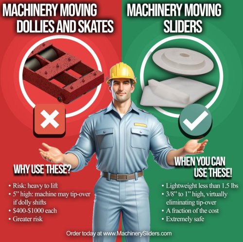
Machinery Sliders provide machinery movers with a non-metallic alternative to conventional steel machinery skates and dollies. The Machinery Slider itself contains absolutely no metal components — no metal wheels, no metal rollers, no bearings, no axles, no steel skate frame, no mechanical moving parts.
The slider is manufactured from a high-performance engineered plastic resin. The pin or bolt used to engage the 1″ center opening is part of the machine/support or retention arrangement and is not a metal component of the Machinery Slider itself.
This distinction allows the Machinery Slider itself to remain 100% non-metallic while still providing the positive retention needed for multidirectional machinery movement.
Multi-Directional Machinery Sliders are designed as wear items. Rather than rolling across the floor on wheels or bearings, the bottom of the Machinery Slider travels directly across the floor. Normal use therefore gradually wears the sliding surface.
The rate of wear depends upon conditions such as machine weight, distance traveled, floor material, floor roughness, cracks and gaps, obstacles, load distribution, and conditions of the individual machinery move.
The slider should be inspected for wear and physical condition and replaced when it reaches the end of its useful service life.
Because the Machinery Slider works by sliding rather than rolling, it contains no wheels, rollers, bearings or axles. There are no wheel bearings to lubricate, rollers to service or mechanical moving assemblies to rebuild.
This simplicity, combined with the lightweight engineered-resin construction, makes Machinery Sliders easy for machinery-moving and rigging crews to carry, position and deploy.
Each Machinery Slider is capable of supporting approximately 10 tons under appropriate loading conditions.
Additional Machinery Sliders can be used when required to support and distribute heavier machinery loads. The correct number and placement of sliders should be determined from the machine’s actual weight, load distribution, center of gravity, support points, floor conditions and the machinery-moving plan. See our Questions & Answers page for the sizing math on larger moves, such as a 100-ton press setup.
Depending upon the load and conditions, Machinery Sliders can be used on many surfaces encountered during industrial machinery-moving work, including concrete, worn or damaged concrete, wood, tile, carpet, dock plates, and asphalt at reduced capability depending upon surface and load conditions.
The 1/2″ beveled perimeter helps the Multi-Directional Slider negotiate many cracks, joints, gaps and floor irregularities encountered during actual machinery moves.
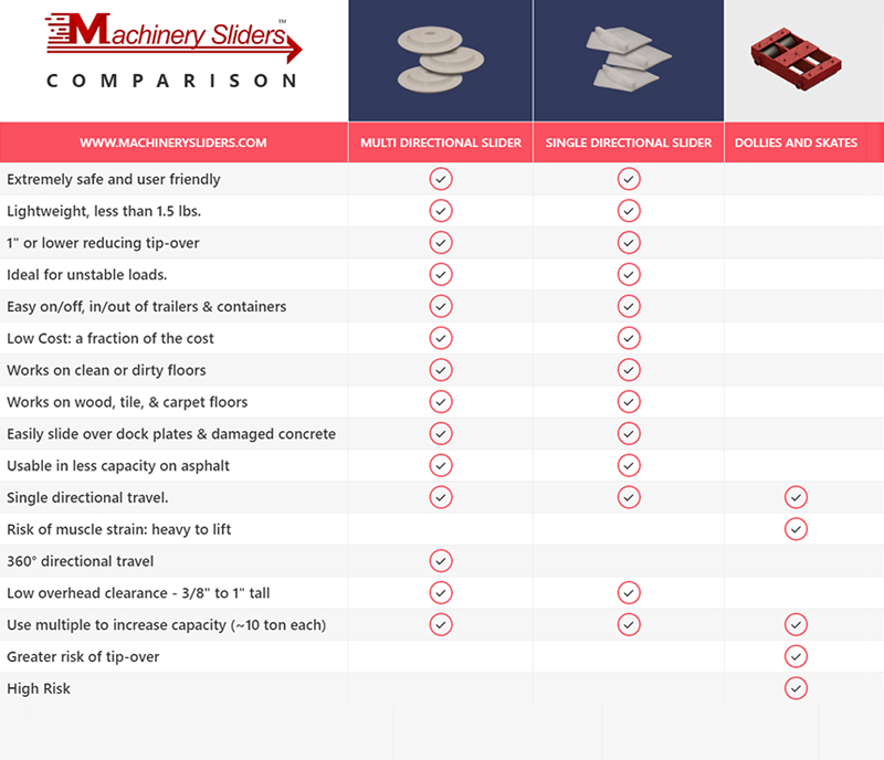
The correct slider depends primarily upon how the machinery must move and how the slider will be retained beneath the machine. See our full Machinery Sliders vs. Dollies & Skates comparison for more detail.
Multi-Directional — 1″ Pin/Bolt Hole
8″ diameter × 1″ high. The machine rests on a 5″-diameter support surface. An appropriate pin or bolt engages the 1″ center hole, positively retaining the slider beneath the machine while allowing movement and positioning in multiple directions. Choose this style when the machine needs to maneuver or change direction and its support arrangement is suitable for the 1″ pin/bolt retention method.
Single-Direction — Reinforced Front Bumper
11-1/2″ long × 8-1/4″ wide × 3/8″ thick. The machine rests on a 7″ × 8-1/4″ support surface behind a reinforced 1″ × 1″ bumper. Choose this style when the machinery primarily travels along an established path and minimum machine elevation is important. See the Single-Direction Machinery Slider.
Multi-Directional — 4″ Machine Leg/Leveling Pad Recess
For machinery with a leveling pad or machine leg up to approximately 4″, the 4″ Foot-Pad Multi-Directional Slider provides another retention method. A 4-1/16″-diameter recess is routed 1/2″ deep into the 1″-high slider. The machine’s pad or leg sits within this recessed pocket, retaining the slider beneath the support point while placing the bottom of the pad or leg only 1/2″ above the floor.
Our photo and video galleries show Machinery Sliders being used by professional machinery movers and riggers on actual jobs throughout the United States — not staged product demonstrations. These real-world examples show Machinery Sliders being used with actual machinery, different floor conditions, clearances and machinery-moving challenges.
See Machinery Sliders on Actual Jobs — Photo Gallery
Watch Machinery Sliders on Actual Jobs — Video Gallery
Choose this Multi-Directional Machinery Slider Set when the machinery must maneuver, turn, reverse or change direction and the machine’s support arrangement allows an appropriate pin or bolt to engage the slider’s 1″ center opening.
If the machine instead has a leveling pad or leg up to approximately 4″, consider the 4″ Foot-Pad Multi-Directional Machinery Slider.
If the job primarily involves one-direction travel, consider the lower-profile 3/8″ Single-Direction Machinery Slider.
For machinery movers and riggers who encounter multiple types of machines and moves, combination sets are available with Single-Direction and Multi-Directional Sliders (8-piece set), or with Single-Direction, Multi-Directional, and Leveling-Pad Sliders (12-piece set).
Set Includes 4 Single-Direction Machinery Sliders — Made in the USA


